 打开微信扫一扫
主营:液压泵,液压马达,液压分流器,单级液压泵,可逆液压泵
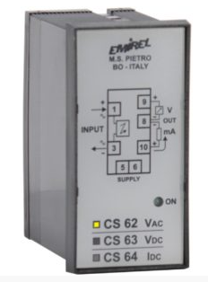
交变电压静态传感器
1500V x 1 min
下的电流绝缘 高达 500 Vac 输入
cs62
功能与性能:
交流/直流电压 V 输出 0-10V 直流 4-20MA
应用:
直流-交流1PH-交流3PH电压控制 PLC配件V
CONVERTITORE
STATICO DI TENSIONE
ALTERNATA
Isolato galvanicamente
(1500 Vac, 1min)
NOTA 1:
Intercambiabile con E 262 cambiando i
collegamenti sullo zoccolo.
DEFINIZIONE
Il dispositivo misura la tensione
alternata Vi presente ai pin 1-3 e la
converte in due uscite: 0÷10V e
4÷20mA (o 0÷20mA). Il legame con le
grandezze di uscita è rappresentato in
fig. 1 e 2.
Modello A (fig.1)
Il dispositivo considera Vi con
escursione da 0 a 100% della tensione
nominale.
Modello B (fig.2)
Il dispositivo considera Vi con una
escursione dal 70% al 130% della
tensione nominale.
UTILIZZAZIONE
Il dispositivo serve per monitorare una
tensione alternata.
INGRESSO: pin 3-1 - 50-60Hz
R ing. = 6 kW/V
(SEPARAZIONE GALVANICA) - fig. 3.
(Per tensione di ingresso 500Vac:
sovraccarico max: 150%).
USCITE:
Tensione: pin 9-8: 0-10V (+ su pin 9).
Carico maggiore 10kW.
Corrente: pin 10-8 (corrente uscente
da pin 10)
Carico max: 500W
Versione 1: 4÷20mA
Versione 2: 0÷20mA
Errore max 1,5% (25°C)
Vi > 1/10 della gamma.
VISUALIZZAZIONI
ON : LED VERDE: alimentazione
presente.
INSTALLAZIONE: vedere fig.3.
(Collegamento a un quadro elettrico
con differenziale e sezionatore).
La lunghezza di ogni collegamento
deve essere minore di 30 m.
SEPARAZIONE GALVANICA
Le alimentazioni della sezione di
ingresso e di uscita sono ricavate da 2
secondari del trasformatore. Le due
sezioni sono separate otticamente
mediante un accoppiatore lineare
senza conversione di frequenza (fig.3).
CS 62
Fig. 1
Fig. 2
Tab. A
CODICE /
CODE
GAMME /
RANGES (Vi Vac)
CS 62 / 1
CS 62 /10
CS 62 /15
CS 62 /20
CS 62 /30
CS 62 /50
CS 62 /58
CS 62 /100
CS 62 /230
CS 62 /250
CS 62 /300
CS 62 /380
CS 62 /400
CS 62 /415
CS 62 /440
CS 62 /500
1V
10V
15V
20V
30V
50V
58V
100V
230V
250V
300V
380V
400V
(*)415V
(*)440V
(*)500V
(*) CS 62 disponibili solo nella versione A
(*) CS 62 available in version A only
ALTERNATE
VOLTAGE
TRANSDUCER
Galvanic insulation (1500 Vac, 1 min)
REMARK 1:
Interchangeable with E 262 by
changing the connections on the male
base.
FUNCTION
The device measures the alternate
voltage Vi at pins 1-3 and converts it
into 0÷10Vdc and 4÷20mA (or
0÷20mA) outputs (voltage, current).
Model A (fig.1)
The operation field ranges from 0 to
100% of the nominal voltage.
Model B (fig.2)
The operation field ranges from 70% to
130% of Vi of the nominal voltage.
USE
It can be used for controlling the AC
voltage.
INPUT: pin 3-1 - 50-60Hz
Input Res. = 6 kW/V
(GALVANIC SEPARATION) - fig. 3
(For input voltage 500 Vac: max
overload: 150%).
OUTPUTS: (max error 1%).
Voltage: pin 9-8: 0-10V (+ on pin 9)
Load higher than 10kW.
Current: pin 10-8 (current outgoing
from pin 10)
Load max: 500W
Version 1: 4-20mA
Version 2: 0-20mA
Max error 1,5% (25°C)
Vi > 1/10 of the range.
VISUALIZATIONS
ON : GREEN LED: supply on.
INSTALLATION: see fig.3.
(Wiring to an electrical board with a
differential relay and a sectionalizing
switch).
The length of every wiring must be less
than 30 m.
GALVANIC SEPARATION
The supplies of the input and output
section are given by two secondaries
of the transformer. The two sections
are optically separated by a linear
coupler, without frequency conversion
ATTENZIONE: Verranno riparati in garanzia, franco ns se
(fig.3).


